7 Tips for Choosing Multi Pair Instrumentation Cable
Choosing the right Multi Pair Instrumentation Cable can protect measurement accuracy long before a signal reaches the control room. A cable may look suitable on a spool, yet perform poorly beside variable-frequency drives, pumps, or long cable trays. Small decisions matter. Pair count, conductor size, insulation, shielding, and jacket material all affect installation and signal quality. One overlooked detail can create noise, awkward terminations, or costly replacement work.
Signal-integrity engineer and author Howard Johnson’s work offers a useful principle, paraphrased here: judge the signal at the receiver, not only at the source. That perspective guides these seven tips. They cover matching pair quantity to current and future circuits, checking conductor resistance and capacitance, choosing appropriate shielding, and assessing voltage and temperature ratings. They also address cable routing, termination practices, and documentation. Practical details count: a drain wire must be handled correctly, and a shield can lose value when installers terminate it inconsistently. Not every site needs the most heavily shielded option. More is not always better.
The best choice depends on the instrument, route, and electrical environment. Start with equipment requirements and actual installation conditions, then compare manufacturer data sheets rather than relying on a familiar label. Ask suppliers for clear test information. Check the details twice. These tips provide a sound starting point, not a substitute for project-specific engineering review. Even careful selection cannot fix poor grounding or careless installation. That part is easy to underestimate.
Understanding Multi-Pair Instrumentation Cable Applications
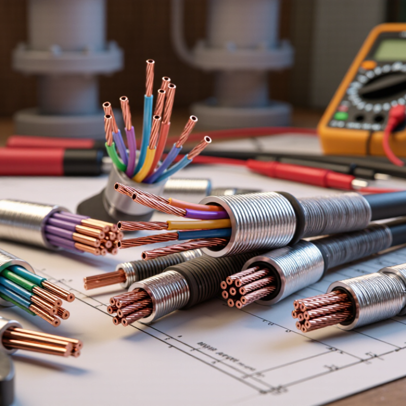
Multi-pair instrumentation cable carries low-level signals between sensors, control panels, and monitoring equipment. Typical applications include temperature probes, pressure transmitters, and process-control loops. Separate twisted pairs help reduce electrical interference, especially when several signals share a route near motors or variable-speed drives. Shielding helps, but it cannot compensate for poor grounding or careless installation.
The U.S. Energy Information Administration’s 2018 Manufacturing Energy Consumption Survey estimated manufacturing energy use at 26.4 quadrillion Btu, including nonfuel uses.
That scale makes dependable measurement important: a noisy signal can obscure a process change or trigger an unnecessary inspection. Cable selection should reflect the actual signal, distance, ambient temperature, moisture exposure, and likely interference. Small signals matter. A shielded cable may suit a noisy plant floor, while a tougher outer jacket may be more important in a damp equipment room.
Tips: Match pair count to current and planned signals, then check conductor size and insulation ratings against the instrument and site conditions. Keep signal cables away from power wiring where practical. Confirm shield termination requirements with the equipment documentation; grounding choices can vary. One detail is easy to miss: spare pairs are useful, but excessive unused cable can complicate routing and maintenance. Do not choose by pair count alone.
Choosing Conductors, Insulation, and Cable Construction
Choose conductor material and gauge from the actual signal, distance, and installation conditions. Copper is common for its conductivity, while the right gauge helps limit voltage drop over long runs. A larger conductor is not automatically better; it can be harder to terminate in a crowded panel. Check the load first. For frequent movement, finely stranded conductors may flex more easily than solid ones. Confirm that the terminals accept the chosen conductor type.
Match insulation to the environment. Its temperature rating should suit expected operating heat, not just room temperature. Check chemical exposure, moisture, and abrasion risks too. A cable near warm equipment or sharp tray edges needs different protection than one inside a dry control cabinet. Small details matter. Also consider insulation thickness: bulky cores can make a multi-pair cable difficult to route and bend.
Review the pair and overall construction before specifying the cable. Consistent pair twists help reduce interference between neighboring circuits; shielding can provide added protection in electrically noisy areas. An individual shield around each pair may help limit crosstalk, while an overall shield can simplify grounding arrangements. Fillers and separators keep pairs in place, and the outer jacket should match the route, such as indoor trays or damp locations. No single construction suits every job. I’ve seen specifications favor extra shielding without considering termination space, and that trade-off deserves a second look. Check bend radius and cable diameter against the installation path.
Checking Environmental, Safety, and Compliance Needs
Before choosing a multi-pair instrumentation cable, map its full route, not just the control-room connection. A section exposed to sunlight, washdown, oil, or changing temperatures may need a different jacket than a protected indoor run. Check the cable’s rated temperature range against both normal operation and brief extremes. Small details matter. A sharp tray edge or repeated movement can damage a jacket over time, even when the cable otherwise suits the environment.
Safety needs deserve the same practical check. Confirm voltage ratings, fire-performance requirements, shielding, and grounding arrangements against the equipment design and project specifications. If the cable passes through a hazardous or high-heat area, verify that its construction is suitable for that location. Do not assume a familiar cable type automatically meets every site requirement. Not always. Ask suppliers for current test reports and product documentation, then compare them with applicable codes, client rules, and installation conditions. Requirements can vary by project and location. It is tempting to specify the most rugged option everywhere, but that may add cost without solving the real exposure. A careful route survey often reveals where extra protection is actually needed.
Comparing Cable Options for Installation and Long-Term Reliability
Choosing multi-pair instrumentation cable means balancing installation practicality with signal stability over years of service. IEC 60228:2023 defines four conductor classes, from solid conductors to extra-flexible strands. Solid conductors can suit fixed routes; flexible classes are easier to handle near vibrating equipment. Check the instrument’s requirements, too: pair count, conductor size, capacitance, and shielding all affect suitability. A smaller cable may fit a crowded tray, but pulling it around a sharp bend can damage insulation.
Tip 1: Compare the cable’s minimum bend radius with the actual route. Tip 2: Match shielding to the interference environment, and plan how shields will be terminated. Tip 3: Verify the jacket’s temperature and chemical ratings against the site conditions. Small details matter. A cable beside a warm motor may age differently from one in a clean, cool control room.
For fire performance, IEC 60332-1-2 specifies a vertical flame test using a 1 kW burner; it does not establish every aspect of a cable’s fire behavior. Review the full test requirements, not just a label. Ask for documented electrical and mechanical ratings, and record the selected cable’s part-free specification in maintenance files. Honestly, field conditions are often messier than the drawings, so leave room for inspection and replacement.