skip to Main Content

What Are Oil Rig Components and How Do They Work?

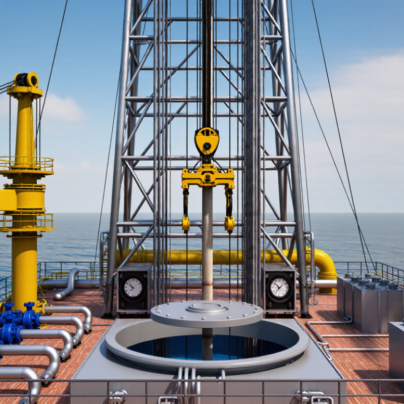
Oil Rig Components form the working system behind drilling operations, from the surface platform to the rock below. Together, they support the rig, rotate the drill string, circulate drilling fluid, and control pressure. On a working rig, the derrick rises above the floor like a steel tower. Beneath it, the drawworks lifts heavy pipe with carefully managed cable tension. The rotary table or top drive turns the drill string, while mud pumps send fluid through the pipe. That fluid returns through the wellbore, carrying cuttings toward the surface. Pressure gauges provide constant visual clues. Small details matter. A worn seal, loose connection, or blocked flow path can affect the entire operation. Real rigs are less tidy than diagrams.

This introduction will examine major Oil Rig Components and explain how they work together. It will cover the mast, substructure, hoisting equipment, power systems, pumps, blowout preventer, drill string, and mud-processing equipment. Each part has a defined purpose, but performance depends on the complete system. For example, the blowout preventer cannot replace careful pressure monitoring, and powerful pumps cannot correct poor fluid design. Safe operation requires trained personnel, inspection records, maintenance planning, and procedures suited to the rig’s location. Offshore equipment faces saltwater, wind, and limited access; land rigs face different transport and ground conditions. Some explanations may simplify complex engineering. That limitation deserves attention. Manufacturer manuals, inspection standards, and qualified engineers remain essential references for real decisions.

What Are Oil Rig Components and How Do They Work?

What Is an Oil Rig and What Purpose Does It Serve?

An oil rig is a large industrial system used to drill wells into the earth. Its purpose is to reach underground reservoirs safely and accurately. It may operate on land, offshore, or on a movable platform. A rig does not usually refine oil. It creates and controls the well that may later produce oil or natural gas.

The derrick supports the drill string, while the drawworks raises and lowers it. A rotary system or top drive turns the drill bit through layers of rock. Mud pumps circulate drilling fluid down the pipe and back to the surface. This fluid cools the bit, carries rock cuttings upward, and helps control underground pressure. The blowout preventer forms a critical barrier above the well. It can seal the well when pressure changes unexpectedly.

Power generators, sensors, control panels, and steel foundations support these operations. In field practice, crews monitor pressure, flow rate, vibration, and equipment condition continuously. Small changes can signal worn components or unstable formations. The work is highly engineered, but it is not perfectly predictable. Even experienced teams can misread early warning signs. A rig’s purpose is therefore broader than drilling deeper. It must protect workers, maintain well control, and preserve the surrounding environment. Some descriptions make rigs appear simple. They are not.

What Are the Main Structural Components of an Oil Rig?

An oil rig’s structure is a load path, not just a tall steel frame. The substructure supports the rig floor, drawworks, mast, and stored drill pipe. It also creates clearance for the wellhead and blowout preventer. That space matters. According to API Specification 4F, mast and substructure design must address rated loads, wind, fatigue, and operational forces.

The derrick or mast rises above the drill floor. It carries the traveling block, hook, and drill string during hoisting. The drawworks controls cable movement, while the rotary table or top-drive system turns the pipe. Steel braces distribute these forces into the foundation or offshore hull. On floating units, pontoons, columns, or hull sections support the deck and drilling package. Fixed platforms transfer loads through jackets and piles into the seabed.

The wellhead anchors the casing and controls pressure. Below it, the BOP stack provides critical shut-in capability under API Specification 53. The IEA’s Oil 2024 report projects global oil demand at 105.4 million barrels per day by 2030, so structural reliability remains commercially important. Yet scale can hide weaknesses. IOGP safety reporting continues to highlight lifting, dropped objects, and process-control risks. A perfectly balanced rig is an attractive idea, but real wells rarely cooperate. Engineers must reassess loads, corrosion, vibration, and weather throughout the rig’s service life.

What Are Oil Rig Components and How Do They Work? - What Are the Main Structural Components of an Oil Rig?

Component System Category Primary Function How It Works Typical Structural or Operating Characteristics Key Loads or Design Considerations
Substructure Primary structural support Supports the rig floor, mast or derrick, drawworks, and well-control equipment above the wellhead. Transfers vertical equipment loads and drilling loads into the foundation, conductor system, or supporting hull. Usually consists of welded steel frames, beams, legs, and bracing. Its height provides clearance for the blowout preventer and wellhead equipment. Must resist compression, lateral forces, vibration, fatigue, wind, wave, and equipment loads.
Mast or Derrick Hoisting structure Provides vertical support for the crown block, traveling equipment, drill string, and tubular handling operations. The structure carries suspended loads while allowing the traveling block to move vertically through its working range. Typically a tall, open-lattice steel structure. A mast is commonly designed to be erected or lowered, while a derrick is generally assembled in sections. Designed for hook load, wind load, dynamic movement, fatigue, and stability during raising, lowering, and drilling.
Rig Floor Working platform Provides the main working area for drilling personnel and supports rotary, pipe-handling, and well-control equipment. Distributes equipment and personnel loads into the substructure while maintaining access around the well center. Includes deck beams, grating or plate flooring, handrails, access points, and openings for tubulars and well-control equipment. Requires slip resistance, drainage, fire protection, safe access, and resistance to concentrated equipment loads.
Crown Block Hoisting system Forms the stationary upper pulley assembly of the main hoisting system. Wire rope is reeved between the crown block and traveling block, multiplying lifting capacity through multiple lines. Mounted at the top of the mast or derrick and fitted with sheaves sized for the drilling line and rated load. Must withstand repeated lifting cycles, line tension, sheave rotation, bearing loads, and fatigue.
Traveling Block Hoisting system Raises and lowers the drill string, casing, completion equipment, and other tubulars. Moves vertically as the drawworks pays out or reels in the drilling line reeved through the crown block. Contains multiple sheaves and is connected to the hook. The block weight and rated capacity vary with the rig's hoisting design. Subject to hook load, acceleration, braking forces, line tension, impact, and fatigue from repeated trips.
Drawworks Hoisting and power transmission Controls the drilling line to lift, lower, suspend, and position the traveling block. Powered drums wind or unwind the drilling line. Braking and control systems regulate block speed and hold suspended loads. Includes a drum, brake system, transmission or drive, clutches or equivalent controls, and drilling-line spooling equipment. Requires reliable braking, heat dissipation, emergency stopping, line management, and protection against overload.
Hook and Swivel Load connection and fluid transfer Suspends the drill string and permits rotation and drilling-fluid circulation through the drill string. The hook connects the traveling block to the swivel. The swivel supports the rotating string while maintaining a sealed fluid passage. Located below the traveling block and above the kelly or top-drive connection, depending on the rig configuration. Must handle tensile load, torque transmission interfaces, pressure containment, wear, and continuous rotation.
Top Drive Drill-string rotation Rotates the drill string and provides a path for drilling fluid while allowing drilling in stand-length sections. An electric or hydraulic motor turns the drill string from a carriage suspended in the mast or derrick. Usually travels vertically along guide rails and integrates a pipe-handler, saver-sub connection, and fluid swivel. Designed for torque, axial load, pressure, vibration, cooling, service access, and reliable control.
Rotary Table Drill-string rotation Rotates the drill string and supports slips when a conventional rotary drilling arrangement is used. A powered table turns a drive bushing that engages the kelly or another rotary component. Slips hold tubulars in the well center. Installed in the rig floor around the rotary opening. It may be the primary rotation device or used alongside a top drive. Must resist torque, axial load, shock, wear, and debris while maintaining accurate well-center alignment.
Mud Pumps Drilling-fluid circulation Circulate drilling fluid down the drill string and back to the surface through the annulus. Reciprocating pistons or plungers draw fluid from the suction system and discharge it at high pressure into the standpipe manifold. Commonly positive-displacement pumps with replaceable liners, pistons, valves, dampeners, and pressure-monitoring equipment. Designed for flow rate, discharge pressure, pulsation control, abrasion, seal life, and safe pressure relief.
Standpipe and Rotary Hose High-pressure fluid piping Conveys drilling fluid from the mud pumps to the swivel or top drive. The standpipe provides a fixed vertical route; the flexible rotary hose accommodates movement of the traveling equipment. Constructed from pressure-rated piping, valves, unions, and flexible hose assemblies suitable for drilling-fluid service. Must withstand internal pressure, pulsation, vibration, movement, erosion, temperature, and connection loads.
Blowout Preventer Stack Well control Seals the wellbore and controls formation pressure during drilling and well operations. Installed below the rig floor on land or on the wellhead system offshore. The stack includes preventers, spools, valves, and control lines. Requires pressure integrity, tested closure performance, hydraulic control reliability, erosion resistance, and safe venting or choke routing.
Wellhead and Casing Head Well support and pressure control Supports casing strings, seals the annulus, and provides the connection point for well-control equipment. Hangers suspend casing, seals isolate annular spaces, and outlets allow monitoring or controlled access to the wellbore. Located at the surface or on the seabed, depending on the drilling unit and well arrangement. Must withstand well pressure, casing loads, thermal effects, corrosion, sealing forces, and installation tolerances.
Drill String Downhole drilling assembly Transmits rotation and weight to the bit while carrying drilling fluid to the bottom of the well. Drill pipe connects the surface equipment to heavy-weight drill pipe, drill collars, bottom-hole assemblies, and the bit. Made from threaded tubular sections with tool joints and specialized downhole components selected for the well profile. Subject to tension, compression, torsion, bending, internal pressure, buckling, vibration, and fatigue.
Casing and Cementing System Wellbore integrity Stabilizes the wellbore, isolates formations, protects groundwater zones, and provides pressure barriers. Steel casing is run into the hole and cement is placed in the annulus to bond the casing to the formation. Casing strings are installed in stages with decreasing diameters as depth increases. Cement placement is verified through testing and evaluation. Designed for burst, collapse, axial load, temperature, corrosion, cement bonding, and formation-pressure differences.
Shale Shakers Solids control Remove large drilled cuttings from the returning drilling fluid. Vibrating screens separate solids by particle size while allowing reusable fluid to pass into the active mud system. Installed near the flowline and mud tanks; screen selection depends on fluid properties, flow rate, and expected cuttings size. Requires vibration isolation, screen integrity, adequate processing capacity, wear resistance, and safe handling of cuttings.
Mud Tanks and Mixing Equipment Drilling-fluid processing Store, condition, mix, and circulate drilling fluid before it is pumped back into the well. Agitators keep solids suspended, while mixing hoppers and chemical-addition systems adjust fluid density and properties. Includes active tanks, reserve tanks, transfer pumps, agitators, level instruments, and fluid-treatment equipment. Must provide adequate volume, containment, corrosion resistance, overflow protection, and accurate fluid monitoring.
Power Generation and Distribution Energy supply Provides mechanical or electrical power for hoisting, rotation, pumping, lighting, controls, and auxiliary systems. Prime movers drive generators or mechanical transmissions, while switchgear and control systems distribute power to major loads. May include engines, generators, fuel systems, electrical panels, transformers, cables, and emergency power equipment. Designed for load changes, redundancy, fuel safety, grounding, short-circuit protection, ventilation, and emissions control.
Marine Hull, Legs, or Jacking System Offshore support structure Supports the drilling package and maintains the unit's position and elevation offshore. Jack-up units use legs and elevating systems; semisubmersibles use pontoons and columns; drillships use a ship-shaped hull and station-keeping system. Configuration depends on water depth, environmental conditions, mobility requirements, and whether the unit floats or stands on the seabed. Must resist wave, wind, current, buoyancy, stability, fatigue, mooring or thruster forces, and storm conditions.
The components and characteristics listed are generalized industry descriptions. Exact capacities, dimensions, ratings, and configurations vary according to rig type, well depth, water depth, and operating conditions.

How Do Drilling Systems Bore Through the Earth?

What Are Oil Rig Components and How Do They Work?

How Do Drilling Systems Bore Through the Earth?

A drilling rig is a coordinated pressure-and-motion system. The derrick supports hoisting equipment above the well. Drawworks raise and lower the drill string. A top drive turns it. Some rigs use a rotary table instead. The string connects heavy drill pipe to the bit. Weight pushes the cutters into rock. Rotation breaks the formation into small fragments. The bit cuts.

Drilling mud makes the cutting process workable. Mud pumps force fluid down the pipe and through tiny bit nozzles. It returns through the annular space around the pipe. The flow cools the bit and carries rock cuttings upward. It also helps control underground pressure. That balance matters. Too little pressure may allow formation fluids to enter the well. Too much can fracture the rock and cause lost circulation.

As depth increases, crews install steel casing and cement. These barriers support the borehole and separate fragile formations. Sensors track torque, temperature, vibration, and fluid pressure. A blowout preventer can seal the well during dangerous pressure changes. Yet drilling is never perfectly predictable. Pressure can shift. A model may miss a weak layer or unexpected fracture. Experienced teams compare live readings with geological plans, then slow down when evidence conflicts. That hesitation can protect equipment, workers, and the well itself.

How Do Power, Circulation, and Control Systems Work Together?

An oil rig works as a coordinated mechanical and electrical system, not a collection of isolated machines. Power usually begins with prime movers and generators, then passes through switchgear to drilling, hoisting, and support equipment. The drawworks lifts and lowers the drill string, while the rotary system transfers torque. Stable power matters. A sudden voltage change can interrupt drilling and strain sensitive controls.

Circulation begins when mud pumps draw drilling fluid from surface tanks. The pumps push mud through standpipes, hoses, and the drill string. It exits through the bit, carries rock cuttings upward, and returns through the annulus. Flow pressure helps cool the bit and maintain well control. If pressure changes unexpectedly, operators investigate the pump, valves, fluid properties, and downhole conditions.

Control systems connect these processes through sensors, programmable logic, alarms, and operator panels. They track pressure, flow rate, temperature, hook load, and equipment speed. Automated interlocks may stop equipment when unsafe conditions appear. Human judgment still matters. A field reading can look normal while a small vibration signals developing wear. No system is perfect. Sensors drift, assumptions fail, and maintenance records may miss early warning signs. Good crews compare instrument data with physical checks, such as unusual heat near a motor or pulsing in a discharge line. When power, circulation, and control signals remain aligned, drilling becomes more predictable, though never completely risk-free.

How Is Oil Extracted, Processed, and Stored on the Rig?

Oil Rig Components and How They Work

Extraction begins below the seabed, where drill bits cut through rock and drilling fluid carries fragments upward. The drill string, mud pumps, and blowout preventer control pressure during this demanding operation. At the wellhead, valves regulate the flow of oil, gas, and produced water. The International Energy Agency’s Oil 2024 report recorded global oil demand at about 102 million barrels per day in 2023. That scale makes reliable separation and measurement essential.

Raw well fluids enter separators on the rig. Inside, pressure reduction allows gas to break away from liquids, while water and solids settle separately. Heaters, dehydrators, and chemical systems help stabilize crude before export. Gas may support power generation or return underground through reinjection. Treated water must meet operating and environmental requirements before discharge. Crude then moves through pumps and metering systems to pipelines, shuttle tankers, or floating storage units. It is not fully refined on most rigs. That distinction is often misunderstood. Storage tanks need level alarms, secondary containment, and regular inspection. Failures can begin with a small leak or inaccurate gauge.

Tips: Check pressure readings against independent meters. Watch rising water cut and vibration trends. The Energy Institute’s Statistical Review of World Energy 2024 shows how large global production remains, but averages hide local problems. Weather, reservoir pressure, corrosion, and human error can change performance quickly. Engineers should document anomalies, question convenient assumptions, and review emergency procedures. The system is sophisticated, yet never flawless.

What Are Oil Rig Components and How Do They Work?

Representative pressure reduction through offshore oil extraction, processing, and storage equipment

Crude oil and associated fluids enter the facility through the wellhead at high pressure. Chokes and manifolds control the flow before the mixture reaches a three-phase separator, which separates oil, gas, and produced water. Additional treatment equipment operates at lower pressure to remove water and gas, while storage tanks usually remain close to atmospheric pressure before export.