
skip to Main Content

How to Choose the Right Ebike Cable?

Choosing the right Ebike Cable can feel like a small decision, yet it affects shifting, braking, and daily riding confidence. A cable that looks suitable may still have the wrong length, housing type, or end fitting. That mismatch can create slow gear changes, stiff levers, or unsafe braking performance.

This guide explains how to compare Ebike Cable options using practical workshop experience and clear technical details. We will examine cable materials, housing construction, diameter, connector styles, and compatibility with different ebike systems. Stainless steel cables often resist corrosion, while coated cables may reduce friction inside the housing. However, neither option fixes poor routing or incorrect sizing.

Measure carefully.

A cable should follow the original path without sharp bends or excessive slack. Check the manufacturer’s specifications when possible, especially for hydraulic systems, electronic controls, and integrated frames. Some products marketed as universal are not truly universal. That is an easy mistake to make.

Reliable selection also requires inspecting the bicycle’s current cable. Look for rust, crushed housing, frayed strands, or delayed lever movement. These details reveal more than packaging claims. Professional installation matters too, because even a high-quality Ebike Cable can perform poorly when cut unevenly or clamped incorrectly. We will also consider weather exposure, riding distance, maintenance habits, and replacement timing. The goal is not to choose the most expensive cable. It is to choose a dependable match for your ebike, riding style, and safety needs.
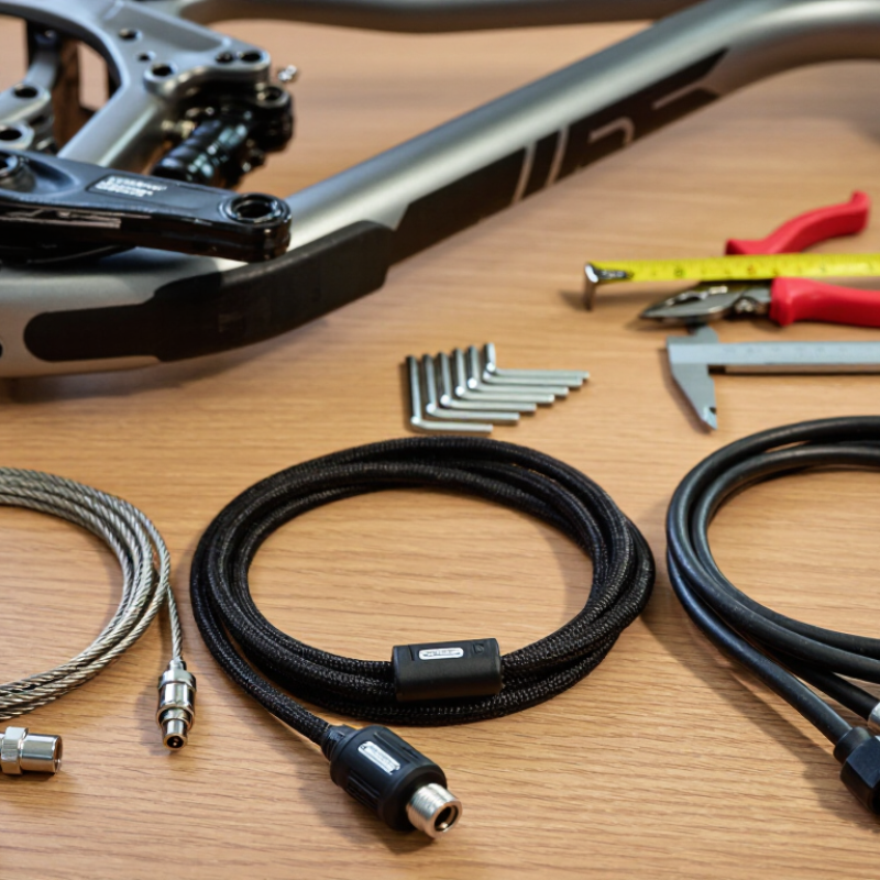
How to Choose the Right Ebike Cable?

Identify the Ebike Cable Type and Its Intended Function

How to Choose the Right Ebike Cable?

Identifying an ebike cable starts with its intended function, not its appearance. A thick cable usually carries motor power. A thin cable may serve sensors, controls, or communication. However, thickness alone can mislead you.

Disconnect the battery first. Then trace the cable from its component to its connector. A motor phase cable often has three substantial wires. A hall sensor cable commonly contains several smaller wires. Brake cutoff cables usually run from the brake levers and use compact connectors. Display, throttle, and lighting cables can look similar, but their pin arrangements may differ.

Check the connector shape, pin count, wire colors, and locking mechanism. Take a clear photograph before removing anything. It helps during reassembly. Never force a connector that feels wrong. A matching plug does not guarantee matching electrical signals.

Cable length matters too. Measure the original route, including bends around the frame. A cable that is too short may strain the connector. One that is too long can rub against the wheel or suspension. Use the same wire gauge whenever possible, especially for high-current motor connections.

In workshop inspections, I also examine crushed insulation and green corrosion near terminals. Small damage can create intermittent faults. That part is easy to overlook. I once considered connector shape enough, but pin layout proved more important. Check the controller manual or a qualified technician when markings are unclear. Guessing can damage delicate electronics.

Check Cable Compatibility with the Motor, Battery, and Display

How to Choose the Right Ebike Cable?

Cable compatibility begins with the motor, battery, and display, not the connector’s appearance. A matching plug can still carry the wrong voltage, current, or signal pattern. Check the battery’s nominal voltage, maximum discharge current, and BMS limits. Then compare them with the motor controller’s input range. The motor cable also needs correct phase and Hall-sensor wiring. A small pinout error can cause vibration, heat, or sudden shutdown.

The display is equally important. Many systems use digital communication, not simple power wires. A cable may fit physically but fail to transmit speed, battery, or error data. The IEA’s Global EV Outlook 2024 identifies electric two- and three-wheelers as a major part of global electric mobility, especially across Asian markets. That scale increases the need for reliable, standardized servicing. Still, standards vary between systems. Do not assume universal compatibility.

Tips: Photograph every connection before removal. Read the controller label carefully. Use a multimeter to confirm voltage and polarity, with power disconnected during continuity checks. Inspect cable length, waterproof seals, and strain relief near the motor axle. I once treated connector shape as proof of compatibility. That shortcut was careless. A wiring diagram is stronger evidence. When specifications remain unclear, pause and ask the supplier for the exact pinout and communication protocol.

How to Choose the Right Ebike Cable? - Check Cable Compatibility with the Motor, Battery, and Display

Cable compatibility depends on the cable’s conductor count and function. Battery power cables commonly use two conductors, motor phase cables use three high-current conductors, Hall sensor cables commonly use five conductors, and display or control cables typically use four or five low-voltage signal conductors. Always verify the connector shape, pinout, wire gauge, voltage rating, and communication protocol before installation.

Compare Cable Length, Connector Design, and Weather Protection

How to Choose the Right Ebike Cable?

Cable length is more important than it first appears. Measure the actual route from the control unit to the motor or display. Follow the frame, not a straight line across the bike. Leave enough slack for steering, suspension movement, and service access. Too little length can pull a connector during a sharp turn. Too much cable can rub against the tire or collect dirt near the crank. I once chose a neat-looking length that became tight after full handlebar movement. That mistake was avoidable.

Connector design deserves close inspection. Match the pin arrangement, key shape, locking method, and wire order. A connector may fit physically but still carry signals incorrectly. Look for a firm locking collar and molded strain relief. These details reduce movement at the cable entry point. For wet commuting, choose sealed connectors with suitable weather protection. Rubber gaskets should sit evenly, without folds or gaps. A drip loop can help water run away from the connection. Wipe mud from contact areas before joining them. Do not force a stubborn plug. Stop and check alignment. Weather resistance is not permanent, especially after repeated bending, pressure washing, or winter salt exposure. Inspect the cable after rough rides, even when everything seems normal.

How to Choose the Right Ebike Cable? - Compare Cable Length, Connector Design, and Weather Protection

Cable Application Typical Length Range Recommended Cable Construction Connector Design to Look For Weather Protection Best Use Case Selection Check
Handlebar Controls to Main Harness 0.6–1.2 m Flexible multi-core cable with fine-stranded copper conductors and abrasion-resistant outer insulation. Compact keyed connector with positive locking; molded strain relief is preferred for repeated handlebar movement. Rain-resistant
Use sealed or gasketed connectors when the plug is exposed.
Display, control pad, remote switch, brake sensor, or throttle connections. Turn the handlebar fully left and right without pulling, twisting, or sharply bending the cable.
Front Light Cable 0.8–1.5 m Two-core power cable sized for the light current; flexible insulation helps prevent fatigue near the fork and head tube. Polarized two-pin connector or sealed circular connector to prevent reversed polarity. Outdoor-rated
Choose a sealed connector if mounted near the front wheel or exposed to spray.
Low-voltage front lamps installed on the handlebar, fork crown, or front rack. Allow enough slack for steering, suspension travel, and accessory removal, but keep the cable clear of the tire.
Rear Light Cable 1.2–2.2 m Lightweight two-core cable with flexible insulation and protective sleeving in areas exposed to frame contact. Locking two-pin connector with clear polarity marking; a waterproof inline connector simplifies service. High exposure
Use sealed joints and route the cable away from direct tire spray.
Rear lights mounted on the seat post, rear rack, fender, or rear frame section. Measure the actual frame route rather than the straight-line distance; include bends around the seat tube and rack.
Motor Phase Cable 0.8–1.8 m Three high-current conductors with thick insulation, abrasion protection, and strong strain relief. High-current keyed connector or direct motor-side termination; terminals should be firmly crimped and insulated. Sealed preferred
Use a sealed connection near the bottom bracket, chainstay, or wheel area.
Connections between a hub motor or mid-drive motor and the controller. Confirm conductor size, current rating, pin arrangement, and connector temperature rating before replacement.
Battery-to-Controller Cable 0.3–1.0 m Two-core high-current cable with insulation rated for the battery voltage and expected continuous current. Polarized, keyed, locking high-current connector with touch-safe contacts; avoid loose friction-fit plugs. Sealed preferred
Protect the connection from water pooling and use a cap when disconnected.
Battery packs mounted on the downtube, rear rack, or frame bag. Match voltage, polarity, continuous current capacity, and connector gender; never rely only on connector appearance.
Controller Extension Cable 0.5–1.5 m Multi-core cable with numbered or color-coded conductors and a durable outer jacket for routing inside or along the frame. Keyed multi-pin connector with locking latch; molded boots reduce bending at the connector body. Moderate protection
Use sealed connectors where the cable exits the frame or passes beneath the downtube.
Extending connections between the controller, display, sensors, and motor harness. Count pins and verify the wiring order; the same number of pins does not guarantee compatibility.
Speed or Wheel Sensor Cable 0.8–1.6 m Small-gauge sensor cable with flexible insulation and additional sleeve protection near the chainstay or fork. Small keyed three-pin or sensor-specific connector with positive retention. Splash-resistant
Use a sealed connection because the cable is commonly routed close to the wheel.
Wheel magnet sensors and speed-sensing assemblies. Secure the cable at regular intervals and maintain safe clearance from spokes, rotors, tires, and suspension parts.
Frame-Internal Cable Routing 1.0–2.5 m Thin-wall, flexible cable with a smooth jacket that can pass through internal guides without excessive friction. Low-profile keyed connectors that fit through the frame openings, or a serviceable connector placed outside the narrowest passage. Entry points sealed
Use grommets to prevent abrasion and reduce water entry through frame openings.
Modern frames with internal routing for displays, batteries, lights, or sensor wiring. Measure the complete routing path and allow service slack at both ends; avoid hidden sharp bends.
Long Cargo or Utility-Bike Run 1.8–3.0 m Flexible cable with abrasion-resistant jacket, robust strain relief, and additional protection where it passes near racks or cargo hardware. Locking, keyed, sealed connectors with secure cable retention. High protection
Select an IP-rated connector assembly only when the rating applies to the fully mated connection.
Long-wheelbase, cargo, utility, or extended-frame ebikes. Route the cable along protected frame sections and prevent unsupported spans that could vibrate or snag.

Lengths shown are typical planning ranges, not universal specifications. Before ordering, confirm the system voltage, current, pin count, wiring order, polarity, connector keying, and mating interface. An IP rating applies only when the complete connector system is correctly mated, sealed, and installed according to its technical documentation.

Evaluate Cable Materials, Durability, and Safety Standards

Choosing the right ebike cable starts with its materials, not its appearance. Fine-stranded copper handles repeated bending better than stiff conductors. Silicone insulation tolerates heat and cold, while TPE offers strong flexibility and abrasion resistance. PVC can work for protected routes, but it may harden near motors or battery housings. Check the cable gauge against current demand, length, and voltage drop. A thin cable may feel neat, yet become warm under sustained load.

Durability depends on the installation environment. Look for sealed connectors, strain relief, and insulation with a clear temperature rating. Water resistance matters around the rear wheel, where spray reaches cable joints. The CPSC reported 208 injuries linked to reported ebike and e-scooter fires from 2017 through 2022. That figure does not prove cable failure, but it supports careful inspection of heat, damage, and poor connections. Small cuts matter.

Safety standards need careful interpretation. UL 2849 evaluates an ebike’s electrical system, while IEC 62133-2 focuses on rechargeable battery safety. Neither standard automatically approves every replacement cable. Ask for documented testing, conductor size, temperature limits, and connector ratings. A cable carrying a familiar marking may still be unsuitable. I once underestimated routing pressure near a hinge; the insulation looked perfect, but repeated bending weakened the conductor inside. Check after installation, not only before it.

Confirm Installation Requirements and Long-Term Maintenance Needs

Choosing the right ebike cable starts with installation requirements, not appearance. Check the motor, controller, display, battery, and brake-sensor connections before ordering. Record connector shapes, pin counts, wire gauge, voltage, and current requirements. A cable may fit physically yet fail electrically. That mistake is easy to make. I once measured only the cable length and missed a locking collar.

Measure the route with the handlebar turned fully left and right. Leave enough slack for steering, but avoid loose loops near the wheel or chain. Check the cable’s bend radius, connector direction, and weather sealing. Waterproofing matters around the head tube and battery area. Use the system’s service manual when pin layouts are unclear. Never force a connector or assume matching colors mean matching functions. Gentle fitting is safer.

Long-term maintenance should be part of the purchase decision. Inspect the cable every few weeks for cuts, crushed sections, corrosion, or stretched insulation. Keep connectors clean and dry, then secure the cable with soft ties. Do not pull the wire when unplugging it. Hold the connector body instead. After riding in rain, dry exposed connections before storage. If a cable becomes warm, intermittent, or unusually stiff, stop using it and arrange a qualified inspection. My own maintenance routine is not perfect, and dirt can hide small damage, so photographing the installation helps during later checks.