Blog
What Is Flexible PCB Material and How Is It Used?
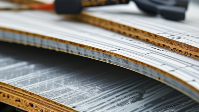
Flexible printed circuits are no longer limited to compact consumer devices. They now support medical sensors, automotive displays, aerospace controls, and wearable electronics. At the center of these applications is flexible pcb material, which allows circuits to bend, fold, and fit into narrow spaces. Unlike rigid FR-4 laminates, flexible materials commonly use polyimide or polyester films, copper foil, adhesive systems, and protective coverlays. These layers must survive repeated bending, heat exposure, vibration, and chemical contact.
Market evidence shows why this technology matters. Grand View Research estimates that the global flexible electronics market reached approximately USD 28 billion in 2023 and may expand strongly through 2030. MarketsandMarkets also identifies flexible electronics as a high-growth segment, driven by smartphones, electric vehicles, healthcare devices, and smart packaging. These forecasts describe a broad market, not flexible PCB material alone. That distinction matters. A large market number can easily create unrealistic expectations.
From practical fabrication experience, material selection begins with the product’s movement, temperature, thickness, and assembly method. A dynamic cable needs different copper and coverlay choices than a static bend circuit inside a camera module. Polyimide offers strong thermal performance, while thinner films improve compactness but may reduce handling tolerance. IPC standards, supplier datasheets, and reliability testing should guide final decisions. IPC-2223 remains a key design reference for flexible printed boards. However, standards cannot replace testing. A circuit may pass visual inspection yet fail after thousands of bending cycles. The best design connects material data with real operating conditions, manufacturing limits, and honest reliability review.
Definition and Core Characteristics of Flexible PCB Material
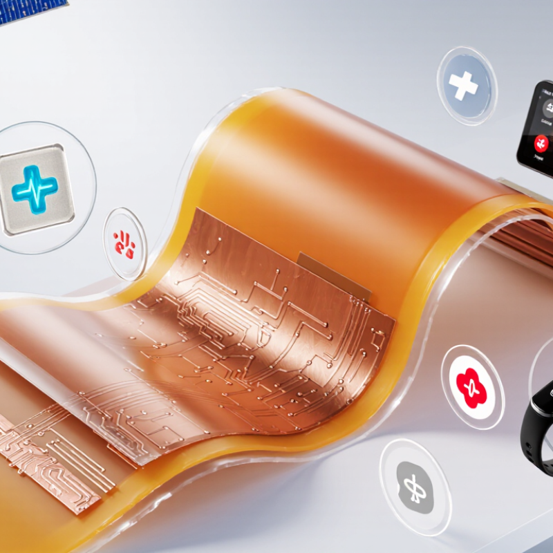
Flexible PCB material is the foundation of circuits that bend, fold, or fit into narrow spaces. It usually combines a polyimide film, copper foil, and protective coverlay. Some designs use adhesive-free structures for thinner profiles and improved heat performance. Polyimide offers strong dimensional stability and reliable insulation across a wide temperature range.
Its core characteristics include flexibility, low weight, chemical resistance, and controlled dielectric behavior. The bend radius matters greatly. A circuit bent too sharply may develop copper cracks, even when the outer film looks undamaged. Static bends and repeated dynamic bends also require different material choices. IPC-2223C provides design guidance for flexible and rigid-flex circuit construction, including bend regions and mechanical stress control.
Market data reflects this growing role. Grand View Research estimated the global flexible electronics market at about USD 29.9 billion in 2023, with strong growth expected through 2030. That expansion includes flexible displays, sensors, medical devices, and compact consumer electronics. Still, market growth does not remove engineering limits. A thinner stack is not automatically better. It may reduce weight while increasing handling risk, impedance variation, or assembly damage. In practical testing, engineers should inspect copper traces after repeated bending, not only measure electrical continuity. That step is often missed.
Main Types and Layer Structures of Flexible PCB Materials
Flexible PCB materials are chosen by bending radius, temperature, signal speed, and assembly stress. Polyimide is the main base film because it remains stable near 200°C and tolerates repeated flexing. Polyester costs less, but it suits lower-temperature circuits with modest mechanical demands. Liquid crystal polymer offers low moisture absorption and strong high-frequency performance, although processing can be less forgiving.
Copper usually appears as rolled-annealed or electrodeposited foil. Rolled-annealed copper bends more reliably because its grain structure supports repeated movement. Electrodeposited copper is often economical for static or limited-flex designs. A 2024 Grand View Research assessment valued the global flexible electronics market at about USD 29 billion in 2023, with rapid growth expected through 2030. That trend increases demand for thinner films, finer traces, and stable dielectric layers. The figure covers flexible electronics broadly, not flexible PCBs alone, so it should not be treated as a direct PCB forecast.
Layer structure controls practical performance. A single-sided flex uses one copper layer and works well for simple sensors or compact interconnects. Double-sided flex adds copper on both sides, with plated vias connecting the layers. Multilayer flex supports dense routing, but each added layer increases stiffness and heat-management difficulty. Rigid-flex construction combines stiff sections with bendable zones, often reducing connectors and assembly space. IPC-2223 and IPC-6013 provide established design and qualification guidance. In production, I would still inspect the bend area closely; standards cannot reveal every crease, adhesive void, or poorly placed via. Thin is useful, but not automatically reliable.
Key Properties That Support Flexible Circuit Performance
Flexible PCB material is selected to bend without losing electrical continuity. The base film is often polyimide because it tolerates heat, repeated movement, and tight assembly spaces. Polyester can serve simpler applications, but its thermal limits require careful review. Copper carries the signal, while a coverlay protects exposed traces from abrasion and moisture.
Flexibility depends on more than the film itself. Rolled-annealed copper usually handles repeated bending better than harder copper types. The bend radius must match the material thickness and circuit structure. A thicker stack-up needs more space to bend safely. Adhesive layers also affect flexibility, heat resistance, and dimensional stability. Small changes matter.
In practical layouts, traces should cross bend zones smoothly. Sharp corners can concentrate stress and cause fatigue cracks. Stiffeners near connectors help prevent unwanted folding during assembly. Controlled impedance may also be necessary for high-speed signals. Moisture absorption deserves attention in compact devices, especially where temperature changes occur.
A common design mistake is treating every flexible area as a hinge. It is not. Dynamic bending, static folding, and vibration create different material demands. Testing should reproduce the real bend angle, cycle count, and temperature. A prototype may pass a gentle hand test yet fail after repeated movement. Material data is useful, but measured performance should lead the final decision.
What Is Flexible PCB Material and How Is It Used? - Key Properties That Support Flexible Circuit Performance
Typical material options and performance characteristics used in flexible printed circuit boards
| Material or Design Dimension | Typical Data | How It Supports Flexible PCB Performance | Common Uses |
|---|---|---|---|
| Polyimide substrate | Continuous-use temperature commonly around −65°C to 200°C; high dimensional stability and strong resistance to chemicals. | Provides reliable insulation, heat resistance, and repeated-flex capability in demanding environments. | Wearables, automotive electronics, industrial controls, cameras, medical devices, and high-temperature assemblies. |
| Liquid-crystal polymer (LCP) substrate | Low moisture absorption, typically below 0.1%; low dielectric loss; melting temperature commonly about 280°C–330°C, depending on grade. | Maintains electrical performance at high frequencies and in humid conditions while supporting fine-line circuit construction. | High-speed data links, compact antennas, radio-frequency modules, and miniaturized electronics. |
| Polyester (PET) substrate | Lower-cost flexible film; typical operating temperatures are commonly limited to approximately 105°C–125°C, depending on construction. | Offers flexibility and economical insulation where temperature and soldering demands are moderate. | Membrane switches, simple displays, low-temperature controls, and cost-sensitive consumer products. |
| Rolled-annealed copper | Copper foil with elongated grain structure; commonly selected in thicknesses from about 9 µm to 70 µm. | Provides good ductility and fatigue resistance for dynamic bending and repeated flexing. | Dynamic flex circuits, hinges, cable replacements, and assemblies that move during operation. |
| Electrodeposited copper | Electroformed copper foil with commonly available thicknesses from about 9 µm to 70 µm; surface treatment may be required for flexing. | Supports economical circuit fabrication and is suitable for static or limited-flex applications when properly designed. | Static flex sections, flex-to-rigid interconnects, and general-purpose flexible circuits. |
| Adhesive-based laminate | Uses an adhesive layer to bond copper foil to the dielectric; total construction thickness depends on copper, adhesive, and substrate layers. | Offers broad material availability and established processing methods, but the adhesive can affect thickness, flexibility, and thermal resistance. | General flexible PCBs, low-to-medium layer-count circuits, and cost-sensitive designs. |
| Adhesiveless laminate | Copper is formed or bonded directly to the dielectric without a separate adhesive layer; supports thinner constructions. | Reduces stack-up thickness and neutral-axis distance, improving bendability, dimensional control, and fine-pitch capability. | High-density interconnects, compact modules, dynamic-flex areas, and lightweight electronics. |
| Coverlay | Flexible insulating film, commonly polyimide, bonded over exposed copper; openings are provided for pads and contacts. | Protects conductors from abrasion, moisture, contamination, and accidental short circuits while preserving flex capability. | Most flex circuits, especially areas exposed to handling or repeated movement. |
| Flexible solder mask | Liquid or film dielectric coating applied selectively to flexible circuit areas; formulation and cure conditions determine flexibility. | Provides solder bridging protection and electrical insulation where a thinner or more digitally patterned covering is preferred. | Fine-pitch assemblies, rigid-flex transition zones, and static-flex designs. |
| Minimum bend radius | A common starting guideline is about 6–10 times the finished flexible-section thickness for static bending and about 20–30 times the thickness for repeated dynamic bending. | Limits copper strain and reduces the risk of conductor cracking, delamination, and premature fatigue. | Cable folds, rotating mechanisms, sliding assemblies, and constrained enclosure routing. |
| Thermal expansion compatibility | Copper has an in-plane coefficient of thermal expansion near 17 ppm/°C; polymer values are generally higher and vary by direction and material. | Material matching helps reduce stress, registration changes, via fatigue, and delamination during thermal cycling. | Automotive, aerospace, industrial, and other electronics exposed to repeated temperature changes. |
| Moisture absorption | Polyimide absorbs more moisture than LCP; exact values depend on grade, film thickness, humidity, and test method. | Moisture behavior affects dielectric properties, dimensional stability, adhesion, and reliability during assembly and service. | Humidity-sensitive high-speed circuits, sealed devices, outdoor electronics, and medical equipment. |
| Flame resistance | Circuit constructions can be designed to meet recognized flammability classifications, such as UL 94 V-0, when the complete material system is qualified. | Improves fire safety and supports compliance requirements for equipment installed near heat sources or enclosed power electronics. | Consumer electronics, transportation systems, industrial equipment, and control panels. |
How Flexible PCB Materials Are Manufactured and Processed
Flexible PCB materials are manufactured for repeated bending, tight spaces, and lightweight electronic assemblies. Polyimide is widely used because it tolerates heat and mechanical stress. Typical base films range from 12.5 to 50 micrometres thick, while rolled copper foil commonly measures 9 to 35 micrometres. These figures vary by design.
Manufacturing often begins with a copper-clad polyimide roll. Clean surfaces matter. Even tiny particles can create open circuits after etching. Engineers apply photoresist, expose the circuit image, and remove unwanted copper through chemical etching. Laser drilling then forms microvias, while electroplating strengthens conductive walls. Industry data from IPC’s flexible-circuit material standards identifies dimensional stability, adhesion, and bending endurance as key qualification concerns. Those properties must be checked after heating, plating, and repeated flexing.
After circuit formation, manufacturers add a coverlay or flexible solder mask. This protects copper while leaving connection pads exposed. Stiffeners may support connectors and reduce assembly damage. Automated optical inspection checks line width and missing features. Electrical testing follows. A 2024 market analysis by Grand View Research estimated the flexible PCB market at more than 20 billion US dollars, with double-digit annual growth expected through the decade. The demand is real, but production is not effortless. Material shrinkage can alter alignment. Adhesive flow can affect impedance. Some designs pass visual inspection yet fail after thousands of bends. Manufacturing teams should test actual bend radius, temperature, and assembly pressure, not rely only on supplier datasheets.
Typical Flexible PCB Material Thicknesses
Flexible PCBs commonly use thin polyimide films, copper foil, and adhesive layers. The representative thicknesses below show how these materials are combined during lamination and circuit fabrication; actual designs vary by electrical, mechanical, and thermal requirements.
Common Applications and Selection Considerations
What Is Flexible PCB Material and How Is It Used?
Common Applications and Selection Considerations
Flexible PCB materials combine a bendable dielectric film with copper circuits and protective cover layers. Polyimide is common because it tolerates heat, repeated flexing, and soldering processes. Polyester costs less, but it suits lower-temperature and less demanding products.
Small and light.
In wearables, flexible circuits fit around curved housings and narrow wristbands. Cameras use them to connect moving lens assemblies without bulky wire bundles. Automotive displays, medical sensors, keyboards, and compact printers also depend on controlled flexibility. Dynamic applications need repeated bending. Static applications only bend during assembly.
Selection begins with the movement pattern. A circuit folded once needs different construction from one flexed thousands of times. Engineers should check minimum bend radius, copper type, trace direction, and layer count. Rolled copper usually supports dynamic bending better than harder electrodeposited copper. Thin copper and staggered traces can reduce stress near the bend.
Temperature, moisture, chemicals, and electrical speed also matter. High-speed signals may require a stable dielectric and controlled impedance. Adhesive-less structures can improve thermal performance, though they may increase cost. Design teams sometimes focus on thickness and overlook the bend radius. That assumption can be expensive. Mechanical testing should match real assembly conditions, including sharp folds, vibration, and connector strain. During validation, record bend cycles, temperature exposure, and failures around connectors.
Related Posts
-
What Is the Best Flexible PCB Material in China?
-
Top China Best PCB Prototyping Solutions for Global Buyers?
-
Why You Should Consider an Electronic Board for Your Next Project?
-
Unlocking the Future of Electronics: The Essential Guide to PCB Production Innovations
-
Solutions for Sourcing the Best PCB Circuit Boards Globally: Your Comprehensive Guide
-

What is PCB Make? A Complete Guide to Designing and Manufacturing PCBs