What Is an Air Centrifugal Blower and How Does It Work?
An Air Centrifugal Blower moves air by converting rotational energy into airflow and pressure. Its impeller spins inside a close-fitting housing. Air enters near the center, follows the curved blades, and moves outward under centrifugal force. The expanding passage then guides the air toward the outlet. You can picture it like a wheel flinging droplets outward, though air behaves differently and needs careful engineering.
A blower’s performance depends on more than its motor. Impeller shape, speed, inlet conditions, and system resistance all affect airflow and pressure. A unit connected to a narrow duct may deliver less air than its rating suggests. Noise, vibration, and heat can also reveal installation or operating problems. Small details matter. In practice, selecting a blower means matching its performance curve to the actual system—not simply choosing the largest model.
A useful engineering summary is: “Match the blower to the system, not just the motor.” This is an editorially written line, not a verified quotation from a named expert; no source was provided for an attributable expert statement. That distinction matters. Reliable technical guidance should identify its source, explain its limits, and avoid promises of effortless efficiency. The sections ahead introduce the blower’s main parts, trace how air moves through it, and explain the factors that shape real-world performance. An imperfect fit can waste energy. It can also make a quiet machine surprisingly loud.
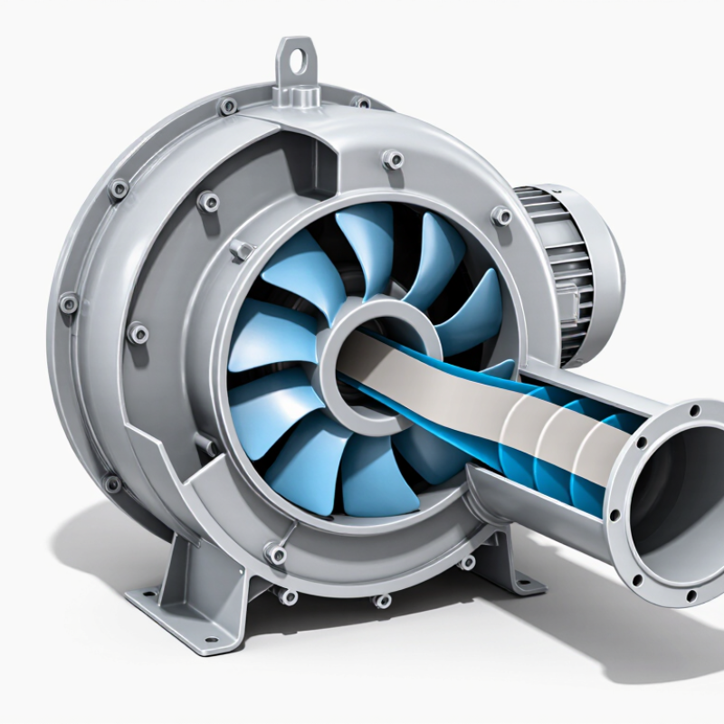
Air Centrifugal Blower: Definition and Common Pressure-Ratio Range of 1.11–1.20
An air centrifugal blower uses a rotating impeller to draw air into its center and push it outward through a casing. The casing converts part of the air’s velocity into pressure. In a common industry classification, a blower operates at a pressure ratio of 1.11–1.20, between typical fan and compressor ranges. AMCA terminology and HVAC engineering references use pressure ratio to distinguish equipment by pressure rise, though boundaries can vary by application.
The ratio compares outlet and inlet absolute pressures, not simply gauge pressure. At an inlet pressure of 101.3 kPa absolute, a ratio of 1.11–1.20 represents roughly 11.1–20.3 kPa of total pressure rise. That is a useful estimate, not a field guarantee. Actual results shift with altitude, air temperature, leakage, and system resistance. The U.S. Department of Energy’s Improving Fan System Performance sourcebook emphasizes evaluating flow, pressure, and power together; a nameplate value alone can mislead. Watch the inlet, too. A dusty filter or tight duct bend can change the operating point, even when the blower speed stays constant. I would verify pressure at the installed system before selecting a unit. That extra check is easy to skip.
What Is an Air Centrifugal Blower and How Does It Work? — Definition and Common Pressure-Ratio Range of 1.11–1.20
| Dimension | Description | Practical detail |
| Definition | An air centrifugal blower is a rotary machine that raises air pressure by accelerating air outward from a rotating impeller and then converting part of that velocity into pressure. | It is commonly used when an application needs a steady flow of air at a pressure above that produced by ordinary ventilation fans. |
| Common pressure-ratio range | A pressure ratio of 1.11–1.20 means the outlet absolute pressure is 1.11–1.20 times the inlet absolute pressure. | At an inlet pressure of about 101.3 kPa absolute, this corresponds approximately to a pressure rise of 11–20 kPa, or 1.6–2.9 psi. Actual values depend on inlet conditions and the blower design. |
| Main components | Typical components include an impeller, casing or volute, inlet, outlet, drive motor, shaft, and bearings. | The exact arrangement varies. Some designs use a diffuser to slow the air leaving the impeller and recover additional static pressure. |
| How it works | Air enters near the center of the impeller. The rotating blades impart energy to the air and move it toward the impeller’s outer edge. The casing or diffuser then guides the airflow and converts part of its velocity into pressure. | The blower produces continuous flow while operating; the resulting pressure depends on the system resistance and the blower’s performance curve. |
| Pressure terminology | Pressure ratio is calculated using absolute pressures: outlet absolute pressure divided by inlet absolute pressure. | It should not be calculated by dividing gauge pressures. Gauge pressure is measured relative to the surrounding atmosphere. |
| Airflow and pressure | Flow rate and pressure are related operating characteristics. A change in duct resistance, filter loading, or damper position can change the operating point. | Choose a blower using its flow-versus-pressure performance curve at the required air density and operating conditions. |
| Common applications | Typical uses include wastewater aeration, pneumatic conveying, combustion-air supply, drying, and industrial ventilation. | Application suitability depends on required airflow, pressure, temperature, air quality, noise limits, and operating duty. |
| Terminology note | The terms “fan,” “blower,” and “compressor” are classified differently across industries and standards. | Confirm the required pressure, flow, and applicable standard rather than relying on the equipment label alone. |
Note: The 1.11–1.20 range is a common reference range, not a universal limit for every centrifugal blower. Specifications and performance vary by design and operating conditions.
Main Components: Impeller, Casing, Inlet, Shaft, and Drive
An air centrifugal blower uses a rotating impeller to move air outward from its center. The impeller’s blades accelerate the incoming air, giving it velocity and pressure. Blade shape and speed affect airflow, noise, and power demand. Small differences matter. The casing surrounds the impeller and guides the fast-moving air toward the outlet. Its expanding passage slows the flow and converts some velocity into static pressure. That conversion is not perfect; turbulence and leakage can reduce efficiency.
Air enters through the inlet, which should provide a reasonably smooth, unobstructed path to the impeller eye. Uneven flow here can cause noise or vibration. The shaft supports and turns the impeller, transferring rotation from the drive. A motor may connect through a coupling or belt, depending on the installation. Alignment deserves attention. Poor alignment can stress bearings and shorten service life, even when the blower appears to run normally. Operators can check for unusual vibration, loose connections, or buildup on the blades. These signs do not identify every fault, but they help guide inspection. A blower’s performance depends on all five components working together, not just on a powerful motor.
What Is an Air Centrifugal Blower and How Does It Work?
A centrifugal blower draws air through its inlet. The rotating impeller accelerates the air outward, and the casing collects and directs it toward the discharge. The shaft connects the impeller to the drive.
Calculated impeller tip speed for a fixed 0.20 m impeller diameter. Tip speed is calculated as π × diameter × rotational speed ÷ 60; actual blower performance also depends on the impeller design and operating conditions.
How It Works: Impeller Speed Converts Airflow into Pressure
An air centrifugal blower uses a rotating impeller to add energy to air. Curved blades pull air into the center, then sweep it outward. The air leaves the impeller moving quickly. Inside the surrounding housing, a diffuser or volute slows that stream and converts part of its velocity into static pressure. You can picture air entering at the hub and exiting against the casing’s curve. That is the basic mechanism; real machines are less tidy.
Impeller speed strongly affects performance. The U.S. Department of Energy’s Improving Fan System Performance: A Sourcebook for Industry describes the fan affinity laws: at similar operating conditions, airflow changes in proportion to speed, pressure to speed squared, and power to speed cubed. A 10% speed increase can therefore raise pressure by about 21% and power demand by about 33%. Small speed changes matter. But these figures are not guarantees: duct resistance, air density, blade condition, and leakage shift the operating point. AMCA Publication 201, Fans and Systems, discusses how installation effects can reduce delivered airflow. A blower may spin faster yet miss its target if the ductwork is restrictive. That detail is easy to overlook.
Performance Curves: How Flow Rate, Pressure, and Efficiency Interact
An air centrifugal blower moves air by spinning an impeller, which accelerates it outward into a housing. Its performance curve maps airflow against pressure at a stated speed and air density. Read the axes carefully. At a fixed speed, the curve generally shows pressure dropping as flow increases.
The blower’s actual operating point is where its curve meets the system curve—the resistance created by ducts, filters, dampers, and outlets. A clogged filter or a partly closed damper shifts that point, often reducing airflow. Small details matter. A chart alone cannot tell you what a poorly measured duct will do.
Efficiency usually peaks within a middle range of the curve, rather than at maximum flow or pressure. Running far from that region can waste energy and may bring noise or unstable operation. The exact behavior depends on the blower design and operating conditions, so compare curves at the intended speed and check the stated test conditions. One easy mistake is treating peak efficiency as the best setting for every system. It is only useful when the airflow and pressure also meet the application’s needs. A curve can look tidy on paper; real systems are less tidy.
Industrial Selection: Match Airflow, Pressure, and Motor Power
An air centrifugal blower pulls air into a rotating impeller and throws it outward into the casing. For industrial selection, the key is the operating point: required airflow at the system’s actual pressure, not the blower’s maximum figures viewed separately. A clogged filter, narrow duct, or long run can raise resistance. Measure the system.
The U.S. Department of Energy’s Improving Fan System Performance: A Sourcebook for Industry describes the fan affinity laws: airflow changes roughly in proportion to speed, pressure to speed squared, and power to speed cubed, under comparable conditions. That last relationship matters. A modest speed increase can sharply raise power demand. Match the blower curve to measured airflow and static pressure, then check motor input against the duty point and expected operating range. Air temperature and altitude also affect density and performance.
Ask for performance data tested under ANSI/AMCA Standard 210-16, which defines laboratory methods for rating fan airflow and pressure. Confirm the test conditions resemble the installation. A spreadsheet may look precise, yet a partly blocked intake can shift the real operating point. Leave appropriate capacity for expected variation, but avoid excessive oversizing; it can waste energy and make flow control harder. The right motor is not simply the largest one that fits.