
skip to Main Content

7 Tips for Choosing Industrial Water Meters

Choosing the right Industrial Water Meters can protect production, reduce waste, and expose hidden process losses. The decision is rarely as simple as comparing pipe sizes or purchase prices. Flow range, water quality, pressure, temperature, installation space, and data requirements all influence performance.

A small mistake matters.

A meter installed near a pump may record unstable flow. Sediment can damage sensitive components. Poor grounding can weaken electromagnetic readings. These details are easy to overlook during a busy plant upgrade. Water-metering researcher Dr. Steven Buchberger has described the meter as “the cash register of the water utility.” His point applies to factories too: unreliable measurement can distort costs, maintenance plans, and sustainability reports.

This guide presents seven practical tips for choosing Industrial Water Meters. It considers accuracy at low and high flow rates, meter technology, pipe conditions, pressure loss, calibration, communication systems, and lifecycle support. Ultrasonic meters may suit clean water and flexible installations. Electromagnetic models can handle conductive liquids without moving parts. Mechanical meters remain useful, but they may require more maintenance in harsh environments.

The cheapest option may not be the most economical.

Real facilities are imperfect. Pipes may vibrate, flow may be intermittent, and installation records may be incomplete. A careful selection process should acknowledge these problems instead of hiding them. Review the application with operators, maintenance staff, and qualified suppliers. Ask how the meter will behave on an ordinary Tuesday, not only in ideal laboratory conditions. Reliable data begins with a realistic understanding of the site.
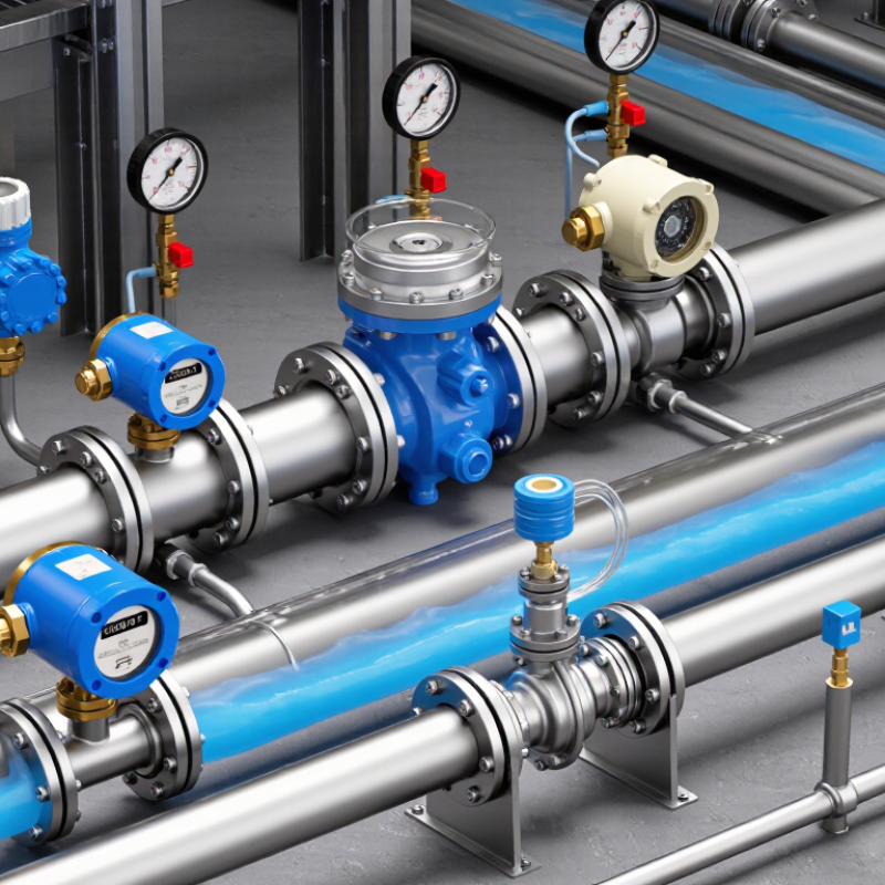
7 Tips for Choosing Industrial Water Meters

Define Flow Conditions: Size for Peak Rates and a 10:1 Turndown Range

Tip: Define the real flow profile before selecting an industrial water meter. Record normal, minimum, and peak rates during production changes, cleaning cycles, and shutdowns. Peak flow determines the meter’s upper capacity, but low flow tests its usefulness. A 10:1 turndown range means the meter can measure peak flow at ten times the minimum flow. For example, a 100 m³/h peak requires reliable measurement near 10 m³/h. Do not assume this range applies equally across every operating condition.

Tip: Size for stable measurement, not simply for the largest pipe. An oversized meter may struggle when demand falls, causing weak resolution and inconsistent readings. An undersized meter can create excessive pressure loss during peak demand. Check the manufacturer’s flow curves, approved velocity limits, and expected pressure drop. Short answer: measure reality. Temporary clamp-on testing or logged pump data can reveal patterns that design drawings miss.

Tip: Review installation conditions before approving the final size. Confirm straight pipe requirements, valve locations, air pockets, and possible flow disturbances. A carefully selected meter may still perform poorly after a nearby elbow or partially closed valve. I have seen clean calculations fail because actual flow was much lower than estimated. That mistake is worth challenging. Use a calibrated reference instrument when possible, and document the lowest dependable flow, not just the advertised turndown ratio.

Compare Accuracy Classes: Target ±0.5% to ±2% Under ISO 4064 Testing

Choosing an industrial water meter begins with its accuracy claim. A ±0.5% reading sounds impressive, but the number can mislead without test conditions. Ask whether the stated error applies across the full flow range or only near the reference point. Under ISO 4064 testing, review the measured error at low, transitional, and sustained flows. A meter showing ±0.5% near peak flow may perform closer to ±2% during overnight demand.

Compare the accuracy class with your process risk. Chemical dosing, water balance, and high-volume billing usually justify tighter control. General utility monitoring may tolerate a wider ±1% to ±2% range. Check the test medium, water temperature, pressure, and installation layout. A nearby valve, short straight pipe, or air pocket can distort results. Small errors compound. Demand evidence.

Look for calibration reports with serial numbers, test points, and uncertainty values. Confirm that the meter maintains its stated performance after filtering, vibration, and changing flow patterns. Installation quality matters as much as the sensor. That is easy to underestimate. An expensive meter cannot correct a poorly filled pipe or an incorrectly sized line. Compare lifecycle accuracy, not only the best percentage printed on a specification sheet. Leave room for doubt, and ask what happens outside the laboratory range.

Match Meter Technology to Conductivity, Pressure, Temperature, and Solids

Choosing an industrial water meter starts with the water itself, not the pipe diameter. Measure conductivity across operating conditions, because electromagnetic meters need a stable conductive path. Ultrasonic meters may suit cleaner water, but air bubbles and suspended particles can weaken their signal. Solids also matter. Sand can wear moving parts, while fibrous debris may obstruct narrow passages.

Pressure and temperature define the meter’s safe working boundary. Check normal pressure, surge pressure, and the highest cleaning temperature. A sensor rated only for routine flow may fail during a pressure spike. Select suitable body materials, seals, and internal linings for the water chemistry. Keep records. These details support safer, more reliable decisions.

Installation conditions can change the result. Long straight pipe sections, full pipes, grounding, and correct sensor alignment help maintain measurement accuracy. In practice, a meter can match the specification sheet and still perform poorly onsite. That is easy to overlook. Test the actual water, confirm the expected flow range, and request traceable calibration data before commissioning. Recheck readings during seasonal changes, especially when conductivity, temperature, or solids vary. A small field mistake can become a large billing or process-control problem.

7 Tips for Choosing Industrial Water Meters - Match Meter Technology to Conductivity, Pressure, Temperature, and Solids

Tip Operating Condition Typical Process Range Suitable Meter Technology Why It Fits Selection Checks
1 Confirm electrical conductivity Clean water: approximately 0.05–2,000 mS/m Magnetic-inductive meter for conductive liquids Measures volumetric flow without moving parts and does not require an obstruction in the flow path. The liquid normally needs conductivity above the meter's minimum specification. Very low-conductivity liquids, such as some demineralized waters, may require another technology.
2 Handle low or changing conductivity Low-conductivity water, condensate, or treated water; often below 50–100 µS/cm Ultrasonic transit-time meter or carefully selected mechanical meter Ultrasonic measurement does not depend on liquid conductivity and can be installed without cutting the pipe when using a clamp-on design. Check pipe material, wall thickness, lining, air bubbles, and straight-run requirements. Verify performance with the actual water quality and flow profile.
3 Match pressure rating to the system Common industrial systems: 6, 10, 16, or 25 bar nominal pressure classes Flanged magnetic, ultrasonic, vortex, or turbine meter with a suitable pressure class A correctly rated body, flange, gasket, and connection protects the meter during normal operation and pressure transients. Select for maximum operating pressure, not average pressure. Include surge, pump start-up, water hammer, vacuum conditions, and the pressure rating of adjacent piping.
4 Check process temperature Typical water service: 0–80 °C; heated water may reach 120–180 °C Meter with temperature-rated liner, electrodes, seals, sensor body, and electronics Temperature affects wetted materials, seal life, electronics location, and the accuracy or reliability of some measurement principles. Specify continuous and maximum peak temperature separately. Consider ambient temperature, insulation, steam cleaning, and whether a remote transmitter is needed.
5 Evaluate suspended solids and abrasives Low solids: below 1%; abrasive slurries can exceed 10% by mass Magnetic-inductive meter for conductive slurry; ultrasonic meter for compatible solids service Magnetic meters have no impeller to clog and tolerate many suspended solids when the lining and electrodes are correctly selected. Assess particle size, hardness, settling velocity, air entrainment, and lining wear. Avoid turbine or paddle-wheel designs where solids can jam or damage moving parts.
6 Size for the actual flow range Design around the normal flow; verify minimum, maximum, and turndown requirements Magnetic or ultrasonic meter with a suitable velocity range; reduced-bore installation where permitted Correct sizing helps maintain measurable velocity at low flow while avoiding excessive pressure loss and over-range operation at peak flow. Record minimum, normal, maximum, and emergency flow. Avoid sizing only from the pipe diameter. Check Reynolds number, velocity limits, accuracy class, and required turndown.
7 Plan installation and maintenance Full pipe required for most inline meters; site conditions vary Inline or clamp-on ultrasonic; magnetic meter with appropriate grounding and straight runs Installation quality strongly affects repeatability, especially where flow is disturbed by pumps, valves, elbows, or partially filled pipes. Provide grounding where required, keep the sensor full, avoid high points that collect air, follow straight-run guidance, and select outputs such as pulse, 4–20 mA, or digital communication.

Note: The ranges shown are general engineering reference values. Confirm the final selection against the meter's certified specifications, local piping standards, fluid composition, and site operating conditions.

Verify Installation Needs: Follow Manufacturer Straight-Run Requirements

Before selecting an industrial water meter, verify the installation space around the pipe. Straight-run requirements are easy to overlook during planning. They directly affect measurement stability and accuracy.

Manufacturers usually specify a minimum length of straight pipe before and after the meter. The required distance depends on the meter design and nearby fittings. Elbows, valves, pumps, and reducers can disturb the water profile. That turbulence may produce fluctuating readings or unnecessary maintenance. Check the installation guide, not just the product dimensions. A compact meter may still require several pipe diameters upstream.

Leave room for inspection. Small errors matter. During field installations, I have seen meters placed too close to a valve because the available space looked sufficient. The pipe fit correctly, but the readings became inconsistent after startup. Measure twice. Confirm the pipe diameter, flow direction, and access for future removal. If the recommended straight run cannot fit, ask a qualified engineer about flow conditioners, repositioning, or another meter configuration. Do not assume a longer downstream section will compensate for a short upstream section.

Record the final layout, including nearby fittings and valve positions. This documentation helps technicians compare future readings with the original installation. It also makes troubleshooting more objective. One practical detail is often missed: temporary hoses and partially closed valves can change the flow pattern during testing. A controlled commissioning check is worth the time, even when the installation appears straightforward.

7 Tips for Choosing Industrial Water Meters: Verify Installation Needs

Recommended straight-run distances vary by meter technology and installation conditions. The values below show commonly specified guidance in multiples of pipe diameter (D); always confirm the final requirements in the selected meter’s installation manual.

How to read the chart: Keep the specified length of unobstructed, straight pipe upstream and downstream of the meter. Valves, elbows, pumps, reducers, and other disturbances may require additional distance or flow conditioning.

Assess Total Cost: Compare 5–10-Year Maintenance, Power, and Data Expenses

When choosing an industrial water meter, purchase price is only the opening line. A reliable comparison should model total cost over five to ten years. Include installation, calibration, seals, batteries, electricity, communication fees, software, and technician visits. Ask suppliers for service intervals and realistic replacement prices. Do not accept vague “low maintenance” claims. Request written assumptions.

Build a simple spreadsheet with annual columns. Record expected energy use in kilowatt-hours and multiply it by your local tariff. Add data expenses, including cellular plans, gateways, storage, and security updates. A meter that costs less today may require frequent site visits or specialized accessories. Small charges become heavy after several winters. Leave a contingency line for unexpected repairs. Real plants rarely follow the brochure.

Check maintenance records from comparable installations, not only laboratory specifications. Ask how readings are verified after pressure surges, sediment buildup, or freezing conditions. Calculate cost per measured cubic meter under normal and peak flow. Also compare downtime risk. A cheap meter becomes expensive when billing or leak detection stops. I have seen budgets fail because labor was ignored. I have also seen cautious estimates waste capital. Revisit the model with actual invoices after the first year, then adjust future projections.